Rendering
Pipeline
Ground
Rules
Objective
Checkpoint (Due Nov 7 at 8pm)
Project (Due Nov 14 at 8pm)
Grading
Procedural Terrain
Parser
Files
A pipeline without
backface culling and without shading computations.
Objective
In this assignment
you will complete the graphics pipeline by implementing the trivial
rejection stage and the illumination stage of the pipeline. The
trivial rejection stage determines if a triangle contributes to
displayed screen pixels. If the triangle is not visible then the
rejection stage removes (culls) invisible triangles by removing
them from the pipeline. Backface culling is a visibility algorithm
for detecting self-occlusion. For this assignment, you will add
backface culling to the rejection stage of the pipeline. The illumination
stage computes the pixel colors for each projected triangle based
on the triangle's surface properties (texture, rougness, etc.)
and the position of light sources. You will implement two illumination
algorithms: flat shading and Gouraud shading.
Checkpoint
(Due November 7 at 8pm)
Add the backface
culling algorithm to the Triangle.illuminate method. If the boolean
variable cull is
true then the back facing triangles should not be illuminated
and the Triangle.culled
variable should be set to true.
Before you can do this correctly, you will have to ensure the
triangle normals are transformed correctly in the Matrix3D class.
As a simple
test to your backface culling algorithm, you can use the cube-no-front.obj
model which removes the front face of the cube in cube.obj. If
your rejection stage is correctly implemented you should not see
the back faces. Note that passing this test is not an indication
that you completed the checkpoint. You should also test your code
in other ways to ensure your implementation works.
Project
4 (Due November 14 at 8pm)
- Extend the
Matrix3D class to transform normals correctly.
- Support
arbitrary number of light sources.
- Implement
backface culling algorithm.
- Support
a directional and an ambient light source (described in Lecture
15).
- Flat shading
with single normal for each triangle (described in Lecture 15).
- Gouraud
shading with a normal for each triangle vertex (described in Lecture
15).
Extra
Credit
- Compute
the specular highlights and demonstrate it with shiny models (described
in Lecture 15).
- Create a
3-D procedural model of mountainous terrain.
Mountainous
Terrain
If you decide
to implement this algorithm, you should first complete the main
project requirements. Recall the midpoint displacement method
for creating terrains: (1) subdivide the triangle by introducing
new vertices at the midpoints of each edge (2) displace the new
vertices by a randomized value. A simple displacement rule would
dependent on the edge size:
d = edge_size * random(-1,
1)
Once your
implementation works, you should experiment with other displacement
rules to obtain different types of terrain.
We suggest
you implement the midpoint displacement method by assuming all
triangle vertices are arranged on a rectangular grid. The size
of the grid (the number of rows and columns of vertices) will
depend on how many times you subdivide the initial grid of four
vertices:
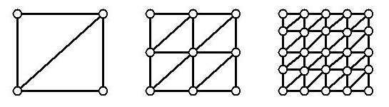
The leftmost grid is the initial grid, with zero subdivisions.
The middle grid is the rectangular grid after one subdivision.
The rightmost grid is the rectangular grid after two subdivisions.
Each subdivision splits existing edges, doubling the number of
edges in each row or column. After m subdivisions the grid
would contain  vertices (one more than the number of edges) in each row and column.
Therefore, if you decide that your terrain will be the result
of 2 subdivisions, just as in the rightmost figure, you should
first create a grid of 5 by 5 Vertex3D elements.
vertices (one more than the number of edges) in each row and column.
Therefore, if you decide that your terrain will be the result
of 2 subdivisions, just as in the rightmost figure, you should
first create a grid of 5 by 5 Vertex3D elements.
Once you
create the grid, you have created all the vertices you will need
for the terrain triangles. Now you have to displace them appropriately.
Notice that the four vertices on the grid corners are the original
vertices of our initial 2 by 2 grid. If one corner vertex is indexed
with (0, 0) then the remaining three corners have indices:

These corner
vertices belong to the initial terrain: after 0 subdivisions.
Therefore, we will call them 0-level vertices. Notice that we
can compute the grid indices of 0-level vertices by incrementing
the row (or column) index by  .
In general, we can iterate through i-level vertices (terrain
vertices after i subdivisions) by incrementing the row
(or column) index by .
In general, we can iterate through i-level vertices (terrain
vertices after i subdivisions) by incrementing the row
(or column) index by  .
Therefore, after m subdivisions, we can iterate through
m-level vertices (all terrain vertices) by incrementing
the row (or column) indices by .
Therefore, after m subdivisions, we can iterate through
m-level vertices (all terrain vertices) by incrementing
the row (or column) indices by  .
Just as we expect. .
Just as we expect.
Your algorithm
should therefore begin by iterating through the four 0-level vertices
(the grid corners) to compute the displaced values of the 1-level
vertices. Once that's complete, the algorithm should iterate through
1-level vertices to displace 2-level vertices and so on until
the m-level vertices are displaced.
At this point,
we have all the vertices in the grid positioned correctly. What's
left is to create Triangle3D triangles to connect the vertices
as in the figure above. Make sure that for each triangle you compute
the normals correctly, and that the triangles are consistently
oriented (in counter-clockwise order).
Files
Pipeline.java
The main applet with parsing support (ReadInput() method) for
object files. Start by looking at the DrawObject method.
Light.java
Defines different types of lights.
Point3D.java
Defines non-vertex 3D points
Vector3D.java
Defines 3D vectors and useful mathematical operations on vectors.
Surface.java
Defines material/surface properties of a triangle: color, shininess,
etc.
Vertex3D.java
Defines a vertex of a triangle. For Gouaraud shading each vertex
has an associated normals.
Raster.java
Slightly different Raster.java from previous assignments. You
should use this version.
ZRaster.java
An
extension of the Raster class to include Z-buffering (depth-buffering)
Triangle.java
Defines a triangle and methods to clip, rasterize, and illuminate
the triangle. You need only modify the Illuminate method: (1)
to set the culled boolean variable correctly for back-facing triangles
(2) to implement the flat and Gouraud shading by computing the
vertex colors appropriately.
Matrix3D.java
Defines 3D transformation matrices. You must ensure that the matrix
transforms normals correctly.
MatrixStack.java
Defines a stack of matrix objects.
cube.obj
A colored cube with a floor.
cube-no-front.obj
Same as a
cube.obj but without the front face to test backface culling.
cow.obj
A purple cow
Parser
Pipeline.java
contains a ReadInput method that parses the object files such
as cube.obj and cow.obj. The object files are parsed as follows:
Comments - # the rest of the line after a pound sign is ignored
Eye Position - eye x y z
Look-at Position - look x y z
World-space up vector - up x y z
Horizontal field-of-view - fov angle_in_degrees
Ambient Light Source - la r g b # color intensities range from
0 to 1
Directional Light Source - ld r g b x y z # x y z is a vector
from the light to the surface
Polygon Vertex - v x y z
Polygon Facet - f i1 i2 i3 i4 ... in # index to vertex 0-based
Surface Parameters - surf r g b ka kd ks nshiney
Ground
Rules
- Feel free
to discuss assignments and your approach with others.
- Don't use
code from previous semesters.
- The design
and code must be your own.
- Cite any
models, images, ideas, or algorithms that you do not develop yourself.
- The assignment
and the checkpoint are due before 8pm of the days indicated.
- A working
version of your applet and source code must be linked to your
course home page.
- All source
code must also be submitted via Athena's turnin procedure.
- Develop
your projects in directories named project1, project2, etc.
(depending on the project number)
- Before
turning in, put your project in a tar archive using tar command
on athena:
tar -cvf projectX.tar projectX
-
here projectX.tar is the archive name, and projectX is
your project directory.
-
X is the project number.
-
make sure you are in the parent directory of projectX
- Use
turnin command to turn in the tar file
turnin -c 6.837 X projectX.tar
Make
sure you include the course number (-c 6.837) and the project
number (X).
- For
example, to turn in project 4:
-
make sure your project is in the directory named 'project4'
-
go to the parent directory of project4
-
type 'tar -cvf project4.tar project4' to create the tar
archive
-
type 'turnin -c 6.837 4 project4.tar' to turn in the archive
- Check
this page frequently for updates and clarifications.
|