Routing
 Settings
Contents:
Routing
Settings
PlacePunch command.PlaceValve command. Valves may be connected together by polylines (preferrably polyline rectangles), in order to be part of the same control line.PlacePunch command.
PlacePunch
The PlacePunch command is accessed by the Micado toolbar button . It prompts the user for a point and draws a punch with the given point as center. The Drawing Settings defines how the punch will be drawn.

PlaceValve
The PlaceValve command is accessed by the Micado toolbar button . It prompts the user to select a point on a flow segment and draws a valve centered on the flow segment near the chosen point. The width and height of the valve are proportional to the width of the flow segment, the exact ratios being defined in the Drawing Settings.
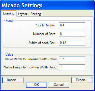
Drawing SettingsThe Drawing Settings are in the Drawing tab of the Micado Settings.
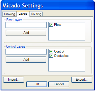
Micado must be told which AutoCAD layers are flow layers and which are control layers. Notably, this is important for routing.
Layers SettingsThe Layers Settings are in the Layer tab of the Micado Settings. A layer is identified by its name. You can add a layer as a Flow layer or Control layer by adding its named, checked, to the corresponding checked box list. To delete a layer from the list of Flow layers or Control Layers, simply uncheck its name in the corresponding checked box list. Note that it's not permitted to have a layer be both a flow and a control layer.
 Routing
Micado automatically routes valves to punches with the ConnectValvesToPunches command, accessible by the Micado toolbar button .
Micado collects entities in the flow and control layers. It groups the control entities into control lines: a control line consists of at least one valve, together with all other entities (valves, punches or polylines) that are connected, directory or indirectly, to that valve. If a control line already has a punch, then it is considered already connected, and will be left alone. The routing command simply attempts to connect each unconnected control line to an unconnected control punch (so the number of unconnected control punches must be at least equal to the number of unconnected control lines). This way, the routing command can be invoked iteratively to connect an already partially connected chip.
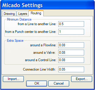
Micado constraints the connections to be legal by the design rules, which are specified in the Routing Settings. In particular,
Routing SettingsThe Routing Settings are in the Routing tab of the Micado Settings. Perhaps, the most important setting is the Minimum Distance from a Line to another Line, as it specifies the resolution of the manhattan grid used for routing. The Extra Space settings are to extend the constraints around the entity boundaries. For example, if extra space around a Flowline is specified, then the constraint of not following or crossing a flowline in a parallel direction is extended to include the extra space around a flowline. Similarly, the extra space around a Valve forbids a connection line from passing too close to another valve.
SettingsAll the Micado Settings are accessible with the command MicadoSettings or the Micado toolbar button .
Each tab in the Micado Settings is discussed in details elsewhere:
For the settings which have units, Micado uses the Insertion Scale of the AutoCAD drawing. To change the Insertion Scale in AutoCAD, select the menu Format, then Units... (The example figures are given in milimeters.)
For your convenience, the settings are persisted from one AutoCAD session to another by being stored in a micado-specific Application Data folder. In addition, you can explicitly export and import Micado settings, in order to share them with your drawings.
Micado automatically generates a programmable Java GUI for your chip. You simply specify the set of instructions to export to the GUI by annotating the flow.
The flow annotations can be
AND specifies that the flow will
split into many branches and be active in all channels at once. OR
specifies that the flow will remain unsplit and will progress down
only one channel, depending on which option the user has selected.
Note that if many OR blocks are composed sequentially, then there is a
combinatorial explosion of the number of options presented to the
user.Once the flow is annotated with names, you create an instruction set by specifying a named flow and an entity on the drawing. The drawing entity becomes the button or set of buttons to run the instruction set.
To support iterative development, flow annotations and instructions are fully re-entrant. You should feel free to edit the drawing and the flow annotations simultaneously.
AppName.png and AppName.dat in javagui/src/, so that the Java application can be built by simply calling build.bat AppName in that directory.For each instruction, the Java program contains a method to call the instruction from your code.
In addition, each instruction set leads to a parameterized method, the arguments being the indices specifying the choices made along the parallel flow paths composed with OR.
Micado can infer the control logic (multiplexers and single valves) needed for the flow annotations to lead to valid flow manipulations.
OR annotation of inputs or outputs, generates a multiplexer if there are at least 4 punches, and if there is enough space for one, and if there aren't any designed valves in that space. Generates all valves necessary to independetly trigger each complete flow manipulation, when they are not redundant with respect to the multiplexers or designed valves.As with the other commands, the generation of control logic supports iterative design by taking into consideration valves that are already on the chip.
Note that, in the current release, pumping is ignored during control inference. Thus, the user should check whether there are enough pumping valves and place some manually if necessary.