6.888 Lab 2: MIMO
Lab 2 Due Friday Oct. 18, 11:59 pm
Introduction
In this lab, you will learn how to decode MIMO signals. The code for
this lab will be written in matlab. We will provide you with a skeleton code. Ideally, you will only need to
modify the places where you see : "... add your code here ..." . We will provide you with wireless signals on
which you can test your code. The lab will be divided into several tasks. Each task will require you to run some
test script which will output a file or plot a figure. You will have to keep the figures and the output files
and submit them along with your src code.
You can download a copy of the lab code here : 6.888_lab2.zip
The code has 4 subfolders:
- SRC_CODE: You need to implement some of these functions.
- Test_Scripts: Code to test the functions you implement.
- Mat_Files: Signals to test your code.
- Results: This folder is initially empty. The test scripts will output files in this folder
The above folders should contain the following files:
| SRC_CODE | Test_Scripts | Mat_Files | Results |
| decode_2x2_mimo.m | test_decode_2x2_mimo.m | Test_2x2_MIMO.mat
Test_2x2_MIMO_R.mat | Result_2x2_MIMO.mat |
decode_1x2_independent.m
decode_1x2_joint.m | test_decode_1x2_mimo.m | Test_1x2_MIMO.mat
Test_1x2_MIMO_R.mat | Result_1x2_MIMO.mat |
decode_2x2_no_alamouti.m
decode_2x2_with_alamouti.m | test_decode_2x2_diversity.m | Test_2x2_MIMO_Alamouti.mat
Test_2x2_MIMO_NoAlamouti.mat
Test_2x2_Diversity_R.mat | Result_2x2_Diversity.mat |
| decode_iac.m | test_decode_iac.m | Test_IAC.mat
Test_IAC_R.mat
Channels.mat | Result_IAC.mat |
| estimate_narrowband_channel.m | . | . | . |
estimate_channel.m
correct_channel.m
rx_ofdm_chain_synced.m
tx_ofdm_chain.m
convert_bin_index_fft_to_normal.m
convert_bin_index_normal_to_fft.m | . | Parameters.mat | . |
In this lab:
- We will assume all channels are narrowband and hence the channel
is flat and can be represented by a single number.
(Note that this is not very realistic for 20MHz channels but we did it to simplify the lab.)
- We will not need packet detection. The signals you are given
already went through packet detection and you can assume that the first sample in
the received signals is the first sample of the packet.
- We do not need to worry about synchronization i.e. CFO and SFO are zero so
CFO estimation and correction and phase tracking are not needed for this lab.
- In the signals we give you, we dropped the preamble part corresponding to
packet detection and CFO estimation. The data symbols however do contain pilots
which we will ignore.
- For this lab, we will only use BPSK modulation.
- We have supplied you with the functions tx_ofdm_chain.m
and rx_ofdm_chain_synced.m from lab1a. They have been slightly
modified since we do not need packet detection or CFO estimation. The script already calls these
function where they are needed.
- Some tests will calculate the BER. To verify whether the BER makes sense you need to
check your estimates of the channel. You can use the built-in matlab function cond( )
to calculate the condition number of the channel matrix.
- The OFDM parameters of this
lab are different than those for lab1. For this lab,
you will use the OFDM parameters shown in the table below.
The variables are stored in the matlab file: Parameters.mat. The code loads these variables into the workspace so you can immediately use them.
| Parameter | Variable | Value |
| Carrier Frequency | fc | 2.45 GHz |
| Sampling frequency | fs | 20 MHz |
| Subcarrier width | w | 312.5 KHz |
| Number of Subcarriers / Symbol length | num_bins | 64 bins / samples |
| Cyclic Prefix | cp | 16 samples |
| Number of data symbols | num_syms_data | 72 |
| Number of data subcarriers | num_bins_data | 48 |
| Number of pilot subcarriers | num_bins_pilots | 4 |
| Pilot Subcarriers | pilots | [-21 -7 7 21] |
| Guard/ Unused Subcarriers | guard_bins | [-32,...,-27, 0, 27,...,31] |
| Preamble Bits | bits_preamble | ... |
| Pilot Bits | bits_pilots | [1 0 1 0] |
Task 1: Multiplexing Gain 2x2 MIMO

In this task, you will implement the RX chain of 2x2 MIMO receiver. The 2x2 MIMO transmitter
transmits 2 packets p1 and p2 on his two antennas. The packets use OFDM and their format is shown
below:

Ideally, we would not transmit the channel estimation symbols except once. However, in this
lab we want to decouple the OFDM RX chain decoding from the MIMO decoding so that you can separate
the two packets p1 and p2 from the two received symbols y1 and y2 and then just feed them into
a standard OFDM decoder from lab 1a.
Start by implementing the function estimate_narrowband_channel.m. This function
should take as input two OFDM symbols in the time domain (two for averaging) and should output a single complex scalar corresponding to the
channel value.
Now implement decode_2x2_mimo.m. It should take two complex signals as
input and should output 2 bit streams. To test your code you can use Test_2x2_MIMO.mat. This
file contains two signals: rx_signal_1 and rx_signal_2
and two output bit streams: bits_data_1 and bits_data_2.
Run the code test_decode_2x2_mimo.m. It will output the file
Result_2x2_MIMO.mat
Task 2: Diversity Gain 1x2 MIMO
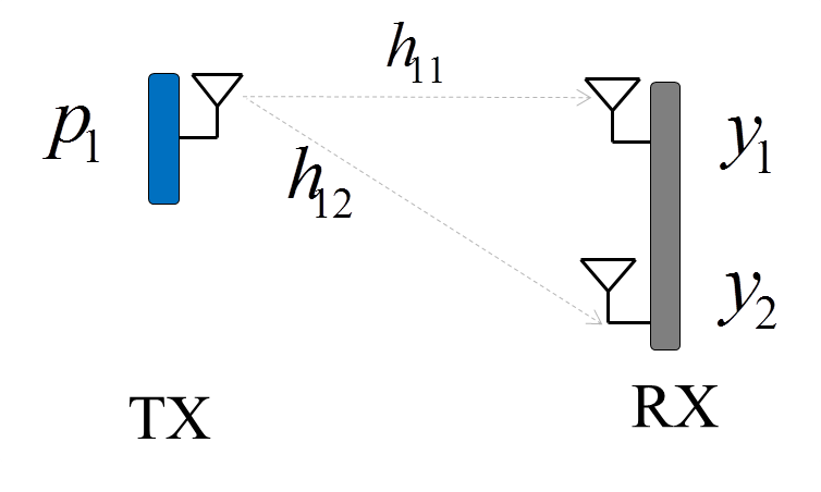
In this task, you will implement the RX chain of 1x2 MIMO receiver. The transmitter
transmits one packet p1. The packet use OFDM and its format is shown
below:

Implement decode_1x2_independent.m. This function will decode the signals
received on the two antennas separately. It should take two complex signals as
input and should output 2 bit streams. If both channels to the receive antennas are good, then
the 2 bit streams should be identical.
Implement decode_1x2_joint.m. This function will decode the signals
received on the two antennas jointly. It should take two complex signals as
input and should output 1 bit stream. To test your code you can use Test_1x2_MIMO.mat. This
file contains two signals: rx_signal_1 and rx_signal_2
and the output bit stream: bits_data.
Run the code test_decode_1x2_mimo.m. It will output the file
Result_1x2_MIMO.mat
Task 3: Diversity Gain 2x2 MIMO

In this task, you will implement the RX chain of 2x2 MIMO receiver with diversity gains.
For the first part of this lab, the transmitter transmits the same data packet on both its antennas. Only the preamble is
different but the data is the same. The packets use OFDM and their format is shown
below:

Implement decode_2x2_no_alamouti.m. It should take two complex signals as
input and should output one bit stream. To test your code you can use Test_2x2_MIMO_NoAlamouti.mat. This
file contains two signals: rx_signal_1 and rx_signal_2
and one output bit stream: bits_data.
Now in the second part of this task, the transmitter transmits the data packet by coding
across symbols using Alamouti code. The transmitter will transmit the packets in the formate shown below.
below:

Implement decode_2x2_with_alamouti.m. The difference
is that now you can no longer mix the two packets into one and use rx_ofdm_chain.m
to decode it. You will have to write your own code to decouple the OFDM symbols. This function should take two complex signals as
input and should output one bit stream. To test your code you can use Test_2x2_MIMO_Alamouti.mat. This
file contains two signals: rx_signal_1 and rx_signal_2
and one output bit stream: bits_data.
Run the code test_decode_2x2_diversity.m. It will output the file
Result_2x2_Diversity.mat
Recall to decode alamouti code:

Task 4: Interference Alignment

In this task, you will learn how to decode signals using interference alignment and cancellation. We have four nodes TX1, TX2, RX1 and RX2.
Each has two antenna. The first transmitter TX1 transmits packet p1 on antenna one and
packet p2 on antenna two. The second transmitter TX2 transmits packet p3 scaled by alpha on the first antenna
and by beta on the second antenna.
In this task, you do not have to do narrow band channel estimation.
All channels have been pre-computed and stored in the file: Channels.mat. The file will also contain the values of alpha and beta which were used align based on the channel values.
The code will load this file.There are 16 different channels. hij will be used as the value of the narrowband channel between
transmit antenna i and receive antenna j. The antenna numbers are labeled in the figure above.
The format of the packets is shown in the figure below:

Implement the function decode_iac.m. The function
should take as input 4 complex signals corresponding to y1, y2, y3, and y4 in the above figure. and output the data bits (you can assume that the pilots are data bits for this task).
To test your code, use the file Test_IAC.mat.
Before you start, load the file Channel.mat and use the values of alpha and beta
to discover along which direction is p3 aligned in RX1.
Since in this task we will use only one set of channel values,
you do not need to write a code that checks the direction of alignment every time.
In decode_iac.m, you can assume you
already know along which direction the interference is aligned.
Then, in decode_iac.m start by projecting the signals received on RX1 on
a direction orthogonal to the interference from p3. This will give you the samples of one of the packets
transmitted on TX1. Decode the bits this packet using rx_ofdm_chain_synced.m.
Next, we want to subtract the samples of this packet from the received signals.
Directly subtracting the samples you have will double your noise. To avoid doubling
the noise, we will re-encode the bits of this packet into clean complex samples that
do not have noise. You can re-encode the bits using tx_ofdm_chain.m.
After re-encoding the packet, we still cannot subtract it directly from the received signals,
you need to scale it by the appropriate channel values. After subtracting this packet from
the received signals, decode p3 from the signals received on the RX2 by projecting on a direction
orthogonal to the interference from TX1 and then subtract this packet from the the signals
received on RX1. Now you can decode the remaining packet on RX1.
- Run the code test_decode_iac.m. It will output the file Result_IAC.mat
Submit:
Submit your code via the class's submission website, located here:
https://haithamh.scripts.mit.edu:444/6.888/handin.py
You may use your MIT Certificate or request an API key via email to log in for the first time.
Compress you folder and name it lab2-handin.zip.
Upload that file to the submission website via the webpage or use curl and your API key:
$ curl -F file=@lab2-handin.zip \
http://haithamh.scripts.mit.edu/6.888/handin.py/upload