<-previous home next->
|
Creating the Line
|
| In this section, I describe how to create a line given two endpoints. |
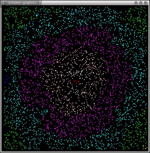
| The amorphous computing model used for the development of this work consists of a two-dimensional surface covered with randomly distributed immobile processors. The processors have circular communication radii with average numbers of neighbors (processors within the same communication radius) between 7 and 8. Simulations were run with between 1000 and 4000 processors all of which were identically programmed and had random number generators. All simulations were created using HLSIM (High Level Simulator). |
Messages |
| In both methods, processors broadcast information to local neighbors on a regular basis. These messages convey the following information.
1)processor-id: Every processor creates an id for itself by choosing a random number. The processor-id is the first part of every message. 2)gradient value Gradients are described in detail in the next section. The gradient value is the second part of every message. 3)state State is a single bit used to identify the role of the processor. If the bit is 1, the processor is part of a line; if the bit is 0 then the processor is not part of a line. State is the third part of every message. 4)successor-id: The id of a neighbor processor that is the best choice to follow in the line. (described further in the next section) This is the fourth and last part of a message. |
Gradients |
| All processors begin with a gradient value of zero. For a processor to initiate a gradient, it simply sets its gradient value to be some positive number, say 50. Every processor that receives a message with this new information will set its own gradient value to be 49. This continues, as every processor that receives a message with the value 49 sets its gradient value to 48 and so forth, until the value reaches zero.
Since the gradient values of processors decrease as you move further away communications wise from the source, a gradient provides us with a useful way of measuring distance between two processors.
In the image the below, the red processor is the source of the gradient, and the different colors of processors represent ranges of gradient values. White processors have the highest values, followed by peach, magenta, cyan, etc. |
|
Growing the Line |
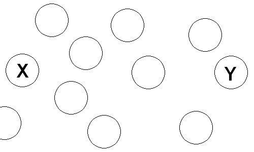
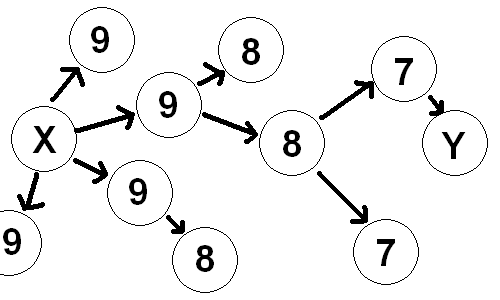
| We begin with two endpoints, X and Y. These two processors know that they are endpoints. Processors are represented by circles. Note that processors can only communicate with other processors within a small communications radius. |
 |
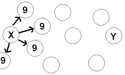
| X originates a gradient, here with a starting value of ten. The gradient propogates from X to Y (left to right in the image below, where the numbers are gradient values). When a processor receives a message from a neighbor with a gradient value higher than it has heard before, it remembers the processor-id from that message. If it then hears an even higher gradient value it forgets this id and remembers the processor-id of the new highest neighbor. This id value is the successor-id and its current value is broadcast in every message. Arrows point from successor to predecessor |
 |
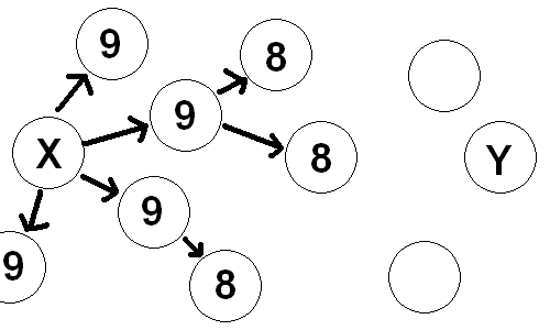
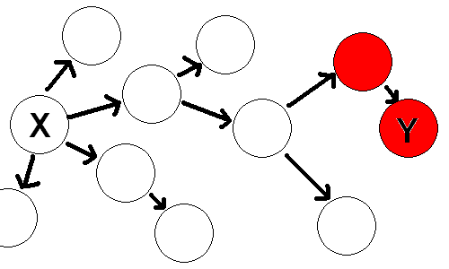
| When the gradient has been propogated, Y sets its state to be 1, indicating that it is now part of a line. (Cells that are part of the line are in red) |
 |
| When the neighbor that is being identified as Y's successor receives a message from Y it recognizes that the successor-id in the message is it's own processor-id. It checks the state value of the message, and since it is 1, indicating Y is part of a line, the receiving processor will set it's own value to be one. |
 |
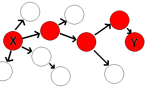
| This process will continue as the successor of this processor follows the same proceedure, until endpoint X is reached. The line simply follows the path that the gradient took to go from X to Y backwards. (Follows the arrows backwards from Y to X) Note that only one such path is possible, since any processor will only ever remeber and broadcast one successor-id. |
 |
| Note that the proceedure above will create the backbone of a line and is only one processor thick, while in the images shown lines are thick. Lines are thick because all the processors within the communication radius of a backbone processor are programmed to change their color to the color of the line so that it is easier to see the line and to tell that it is indeed connected. |
<-previous home next->