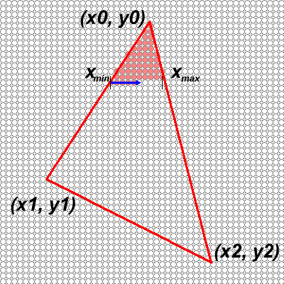
In this project you will build a triangle scan converter that uses an edge-walking approach. Edge-walking rasterizers proceeds from the top-most vertex, and scan convert from top to bottom. They keep track of the two active edges which determine the current span.
Notice that the edge of a triangle seldom passes exactly through a pixel. For the purposes of this assignment a correct rasterization will be defined as one where all the pixel centers contained within the ideal edges are turned on.
Your triangle scan converter must also interpolate the vertex colors inside of the triangle. While, you are not allowed to use the edge-equation triangle rasterizing approach covered in class to scan convert your triangles, you can use plane equations to interpolate the colors. While, it is slower to use plane equations for interpolation, it is tricker to interpolate colors down the edges (A fair warning).

Your method should have the following interface and use the following Vertex2D data structure.
public class Vertex2D {
    public float x, y;              // coordinate of vertex
    public int argb;                // color of vertex
    public Vertex2D(float xval, float yval, int cval)    {
        x = xval;
        y = yval;
        argb = cval;
	}
}

public triangle(Vertex2D v0, Vertex2D v1, Vertex2D v2);
In addition to the triangle method your applet must also be able to read in a triangle file. Each line of the file will be formatted as follows:
x1 y1 color1 x2 y2 color2 x3 y3 color3
x1 y1 color1 x2 y2 color2 x3 y3 color3
x1 y1 color1 x2 y2 color2 x3 y3 color3
		.
		.
		.
Where xn and yn are strings representing legal floating point values, and colorn is a string possibly with a "0x" prefix (hint: look at java.lang.Integer.decode()) representing an integer. The triangles should be rendered in the order given by the file.
You can use the following files to get started:
The test applet works as follows:
The applet first displays the reference image. After pressing the first mouse button, the applet will render the triangle list using your triangle rasterizer and display it. One more mouse click will cause a difference image to be displayed (blue pixels represent small errors, red pixel indicate large errors, and the hues of the spectrum indicate errors in between). Several statistics are provided along with the difference image, including the number of pixels that did not exactly match those in the reference rendering, the average deviation of an errant pixel, and how long the rendering took. Additional mouse clicks cause the process to repeat. |
Go for speed, I will provide a timing function as part of my test applet.